As you may have guessed we're about to replace one of our resistors with a potentiometer, so we can easily adjust the gain. So here's a little potentiometer review:
Next we're going to wire up our potentiometer, just to get comfortable with the wiring here. Don't worry about the formula and the math yet, we'll go over that in the following video.
Note that in the next video I suggest using multiple different colors of wire, to make it easier to see where all your wires are going as your circuits get more complicated. That said, please don't use blue wire! Just like how you use red and black for power and ground, there's going to be a very specific purpose for that, which you'll see in an upcoming lesson.
At the end of the last lesson I encouraged you to try to change out some of the resistors in the circuit and see the gain changing accordingly. And I mentioned that the op amp has the notable limitation that it can't output a voltage higher than the voltage of your power supply. And in fact, often with common and inexpensive ones like the LM358, it's maximum output voltage is a little less than your power supply voltage.
In the video below I make an amplifier that allows me to crank the gain up so high that the output reaches and gets stuck at that maximum output voltage.
In the video I replace our 10k resistor for R1 with a 1k. You should do this too, since this will be useful for creating the extremely high gain we need for the distortion effect we're slowly building.
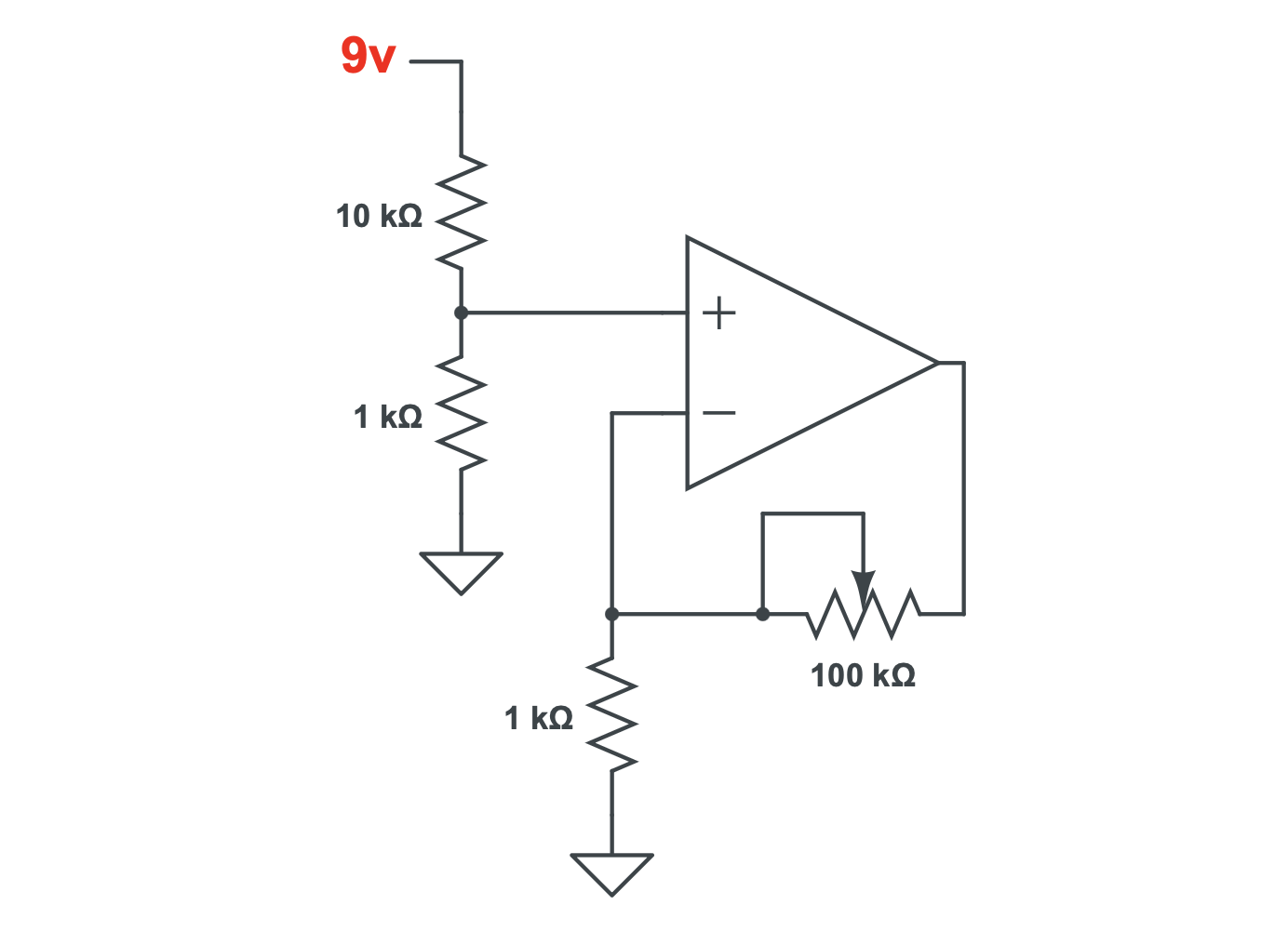
This is probably a good time to mention that any time you only use two pins of the potentiometer, as we did in this circuit, you draw the symbol like either one of these, it doesn't matter which one: